Beyond Data The Evolution and Underlying Mechanisms of RJ45 & PoE Technology
In-depth Analysis: RJ45 Interface and PoE (Power over Ethernet) Technology
In the landscape of modern network infrastructure, the
RJ45 interface has evolved from a simple data gateway into a sophisticated medium for simultaneous data and power delivery.
Power over Ethernet (PoE) technology leverages standard twisted-pair cabling to provide DC power to devices without altering the existing physical link structure.
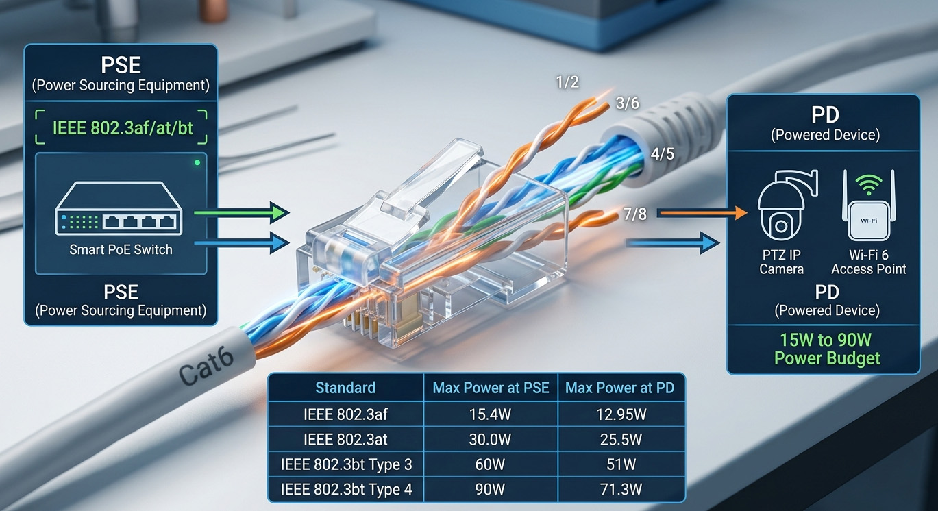
I. Core Architecture: PSE vs. PD
The PoE ecosystem operates through two primary functional roles:
-
Power Sourcing Equipment (PSE): Devices like PoE switches or Midspan injectors that manage power detection, injection, and monitoring.
-
Powered Device (PD): Devices such as Wireless APs, IP cameras, and VoIP phones that receive and convert the transmitted power for operation.
II. Evolution of IEEE Standards
PoE technology has advanced through several iterations to meet increasing power demands:
|
Standard
|
Designation
|
PSE Output
|
PD Input
|
Typical Applications
|
|
IEEE 802.3af
|
PoE
|
15.4W
|
12.95W
|
VoIP phones, basic IP cameras
|
|
IEEE 802.3at
|
PoE+
|
30W
|
25.5W
|
PTZ cameras, Dual-band APs
|
|
IEEE 802.3bt
|
PoE++ / 4PPoE
|
60W – 90W
|
51W – 71.3W
|
5G Small cells, Laptops, Smart Lighting
|
III. Operational Logic: The Handshake Process
To ensure hardware safety, standardized PoE follows a rigorous "Handshake" sequence before applying full voltage:
-
Detection: The PSE sends a low voltage to detect the signature resistance of a PD.
-
Classification: The PSE determines the power class of the device to budget its power pool accordingly.
-
Startup & Monitoring: Once validated, the PSE delivers ~48V DC. It continuously monitors the current; if the device is unplugged, power is cut immediately to protect the port.
Crucial Note: Passive PoE (Non-standard) skips this handshake and delivers power "always-on." Connecting a non-PoE device to a passive PoE port can lead to permanent hardware damage.
IV. Physical Layer & Cabling Requirements
-
Cable Grade: To minimize resistive heating and voltage drop, Oxygen-Free Copper (OFC) cables are mandatory. Cat5e is the minimum, while Cat6 or Cat6A is recommended for high-power (802.3bt) applications.
-
Transmission Limit: The maximum effective distance remains 100 meters (328 ft). Beyond this, PoE extenders or fiber-to-PoE media converters are required.
-
Heat Dissipation: In large-scale deployments, cable bundling can lead to heat buildup. Proper ventilation and choosing cables with higher temperature ratings are essential for maintaining signal integrity.
V. Strategic Advantages & Deployment Tips
-
Deployment Flexibility: Eliminates the need for AC outlets at every endpoint, allowing for optimal placement of sensors and APs.
-
Centralized Management: High-end PSEs allow administrators to remotely power-cycle devices via a web interface or CLI, significantly reducing "truck rolls" for maintenance.
-
Power Budgeting: When selecting a PoE switch, always calculate the Total Power Budget against the peak consumption of all connected PDs, leaving a 15-20% margin for stability.
PoE technology, through the ubiquitous RJ45 port, continues to be the backbone of "Smart Building" and Industrial IoT (IIoT) initiatives by simplifying the convergence of power and intelligence.