HomeResources
Essential Guide to RJ45 Ethernet Circuit…
Essential Guide to RJ45 Ethernet Circuit Design: Architecture and Layout Best Practices
In the field of hardware engineering, the RJ45 Ethernet interface circuit is a critical communication module. A robust design ensures signal integrity, electromagnetic compatibility (EMC), and electrical safety.
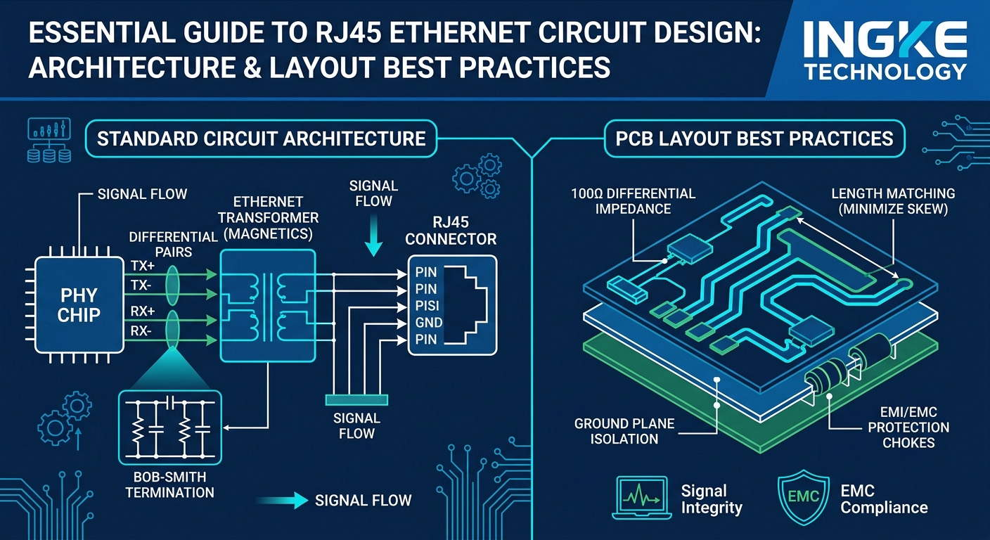
A standard Ethernet circuit consists of four primary blocks: MAC Controller (often integrated into the SoC), PHY (Physical Layer Transceiver), Magnetic Transformer, and the RJ45 Connector.
1. Hardware Architecture Overview
There are two common hardware implementations in modern designs:
Discrete Solution: CPU (MAC) + PHY Chip + Discrete Transformer + Standard RJ45 Socket.
Integrated Solution (MagJack): CPU + PHY Chip + Integrated Connector Module (ICM), where the transformer and LEDs are built directly into the RJ45 housing. This is preferred for space-constrained designs and better EMI performance.
2. The Role of the Magnetic Transformer
The "Magnetics" are the most vital part of the circuit, serving three main purposes:
Electrical Isolation: It provides up to 1500V isolation between the PHY chip and the external cable, protecting the sensitive silicon from ground loops and high-voltage surges.
Common-Mode Suppression: Integrated common-mode chokes filter out high-frequency noise from the differential pairs.
Bob-Smith Termination: The center taps of the transformer are typically connected to a Bob-Smith circuit (75Ω resistors and a high-voltage capacitor to ground). This matches the common-mode impedance of the CAT5 cable, significantly reducing EMI radiation.
3. Key Differences: 10/100 Mbps vs. 1000 Mbps (Gigabit)
Feature
10/100Base-T (Fast Ethernet)
1000Base-T (Gigabit Ethernet)
Pairs Used
2 pairs (Pins 1-2 TX, 3-6 RX)
All 4 pairs (1-2, 3-6, 4-5, 7-8)
Signal Type
Differential, Single-direction per pair
Bi-directional on all 4 pairs
Encoding
MLT-3 / Manchester
PAM-5 (5-level Pulse Amplitude)
4. Critical PCB Layout Guidelines
To ensure stable data transmission, the following layout constraints are mandatory:
Differential Impedance: Trace pairs must be routed with a
differential impedance.
Length Matching: Intra-pair skew (the length difference between P and N lines) should be kept within 5 mils to prevent signal phase shifts.
Isolation Gap (Moat): A physical clearance (void) should be maintained in the ground plane beneath the transformer or MagJack. This separates the Chassis Ground (RJ45 side) from the Digital Ground (PHY side) to prevent external noise from entering the system.
Component Placement: The distance between the PHY chip and the Magnetics should be as short as possible (ideally under 1–2 inches) to minimize signal attenuation and crosstalk.
5. Conclusion
The design of RJ45 Ethernet port circuit is not only about simple "wiring", but also involves complex considerations of EMC suppression and signal integrity. In practical engineering, it is crucial to prioritize the use of integrated RJ45 modules from well-known manufacturers such as Pulse, Halo, WE, INGKE, etc., and strictly follow the reference design in the PHY chip manual to ensure product reliability.