HomeResources
RF Frequency and Impedance Matching: Cor…
RF Frequency and Impedance Matching: Core Logic of High-Frequency Design
In RF (Radio Frequency) design, Frequency and Impedance are the two fundamental pillars that determine system performance. Unlike low-frequency circuits where wires are treated as ideal connections, high-frequency signals behave as waves, making any impedance mismatch a source of signal degradation.
The Art of Balance: Deep Dive into RF Frequency and Impedance Matching
In the RF domain, once the signal wavelength approaches the physical dimensions of the circuit, impedance is no longer just a resistance value but a complex quantity( Z = R + jX ) consisting of resistance, capacitive reactance, and inductive reactance.
1. The Impact of Frequency on Impedance
As the operating frequency increases, "parasitic parameters" that are negligible at DC begin to dominate circuit behavior:
Skin Effect: At higher frequencies, current tends to flow on the surface of the conductor. This reduces the effective cross-sectional area, causing the RF resistance to increase with frequency.
Parasitic Inductance & Capacitance: Connector pins and PCB traces exhibit inductive reactance at GHz levels, while parasitic capacitance between layers can lead to signal leakage.
Dielectric Loss: The energy absorbed by insulation materials under alternating electric fields increases with frequency, directly affecting signal reach.
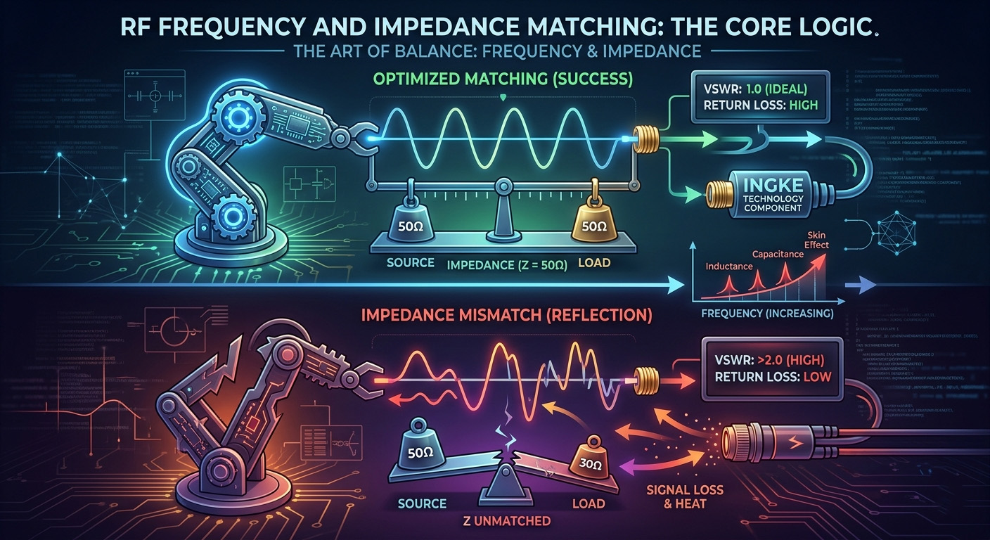
2. The 50Ω Standard and Matching Logic
Why is 50Ω the universal standard for RF systems?
It is a strategic compromise: 30Ω offers the highest power-handling capability, while 77Ω offers the lowest transmission loss. 50Ω is the industry-accepted "sweet spot."
The Goal of Matching: When the source, transmission line, and load impedances are identical, energy transfer efficiency is maximized, and reflections are minimized.
3. Reflections and VSWR
Impedance discontinuity causes signals to "bounce back" at the interface, creating standing waves:
Return Loss: Measures the energy reflected back to the source. A higher value indicates better matching.
VSWR (Voltage Standing Wave Ratio): An ideal value is 1.0. In high-performance RF systems, a VSWR below 1.2 is typically required to ensure stability.
4. Engineering Solutions by INGKE TECHNOLOGY
To maintain constant impedance across varying frequencies, INGKE TECHNOLOGY integrates advanced precision techniques into its connector designs:
Structural Compensation: By fine-tuning the internal diameter and geometry of pins, we compensate for impedance jumps at physical transitions.
Low-Loss Dielectric Selection: We use materials with a low Dielectric Constant (Dk) and Dissipation Factor (Df) to ensure flat impedance curves across wide bandwidths.
Full-Link Simulation: Utilizing 3D electromagnetic simulation tools, we optimize impedance continuity at every transition point to suppress high-frequency reflections.
5. Conclusion
In RF design, frequency sets the rules, but impedance dictates the success. By utilizing precision components from INGKE TECHNOLOGY, engineers can significantly reduce link discontinuity and enhance the signal integrity of the entire communication system.